
- 021-58765400
- CN

The SecoGear series is a compact air‑insulated switchgear with innovative design, representing industry‑leading levels in safety, reliability, performance and sustainability. Certified by national authoritative test institutions in accordance with GB/T 3906 and IEC 62271‑200 standards for AC metal‑enclosed switchgear.
The SecoGear P/V switchgear is capable of controlling and protecting commonly‑used industrial equipment such as cables, transformers, capacitors and motors. The SecoGear P/V excels in all medium‑voltage power switching, control and protection applications.
Product Features
- Indoor‑type general‑purpose switchgear with high safety and reliability
- Equipped with the latest solid‑pole‑mounted SecoVac VB2 Plus vacuum circuit‑breaker
- Cable compartment with sufficient space for convenient cable connection
- Internal arc‑fault classification up to AFLR, maximum 40 kA/1 s, 50 kA/0.5 s
- Tests comply with both GB and IEC standards
- Complete interlocking system to prevent incorrect operations and enhance safety
- Seismic withstand level reaches AG5 for 12 kV and below, AG3 for 24 kV
- Indoor AC metal‑enclosed switchgear; compact‑design air‑insulated switchgear for various transformer and distribution substations
Product Qualities
The SecoGear P/V series has passed type‑tests by national authoritative test institutions in accordance with GB/T 3906 and IEC 62271‑200 standards. The SecoVac series vacuum circuit‑breakers have also obtained type‑test certifications from national authoritative test institutions complying with GB/T 1984 and IEC 62271‑100 standards. The P/V series is equipped with circuit‑breakers of this series.
Adopting advanced technologies and manufacturing processes of the highest‑quality standards, our engineers have integrated core technologies. Combining circuit‑breaker, mechanism design, vacuum arc control technology, insulation technology, as well as electric‑field control and analysis technologies, a highly‑reliable compact system has been developed. The SecoGear P/V series incorporates state‑of‑the‑art medium‑voltage technologies.
SecoGear P/V‑12 has rated voltages of 3.6/7.2/12 kV, with rated current ranging from 630 A to 5000 A (forced‑air cooling is required for 4000 A and above). For SecoGear P/V‑24, the rated current ranges from 630 A to 3150 A (forced‑air cooling is required at 3150 A).
All SecoGear switchgears are fitted with SecoVac VB2 Plus vacuum circuit‑breakers of corresponding specifications.
-


IP rating
The IP protection level represents the solid and liquid impermeability of the SecoGear P/V series, and the protection level is indicated by the IP prefix followed by two characters. The protection level of the shell is IP4X, and the protection level between different compartments inside the cabinet is IP2X.
-


High ambient temperature
The usage conditions of electrical equipment applied to ships are much more severe than those on land. Temperature is one of the important factors, therefore the shipping registration regulations require switchgear to be able to operate at higher ambient temperatures (40 ° C or higher). If the ambient temperature exceeds 40 ° C, please contact the local sales engineer.
-


Efficient and energy-saving assembly
The production environment of the SecoGear series is efficient and energy-saving. The design process and material standards used do not require special processing or manufacturing processes, thereby reducing energy consumption during the manufacturing and assembly of switchgear.
-


Efficient use of materials
In addition to energy, we also pay attention to the efficiency of material usage during the assembly process. For example, cutting aluminum zinc steel plates using advanced nesting tools generates the least amount of waste. The design and manufacturing of other product components also follow similar guidelines.
-


The lowest number of on-site inspection services
The SecoGear series has a lifespan of up to 20 years; But throughout the entire lifecycle, maintenance consumes the lowest amount of energy. Thanks to its green insulation and switch technology, there is no risk of harmful SF6 gas leakage during its lifecycle, and no additional SF6 gas pressure inspection and maintenance are required.
-


Reuse or recycle materials
All materials used in the SecoGear and SecoVac series are reusable and have no adverse effects on the environment. This fully reflects our social responsibility in product design and production.
-


Minimize energy loss during operation
The number of overlapping surfaces or transition points in the SecoGear system is definitely the smallest. This reduces the number of potential "hotspots" and minimizes additional energy loss on the contact surface.
Product Performance and Parameters
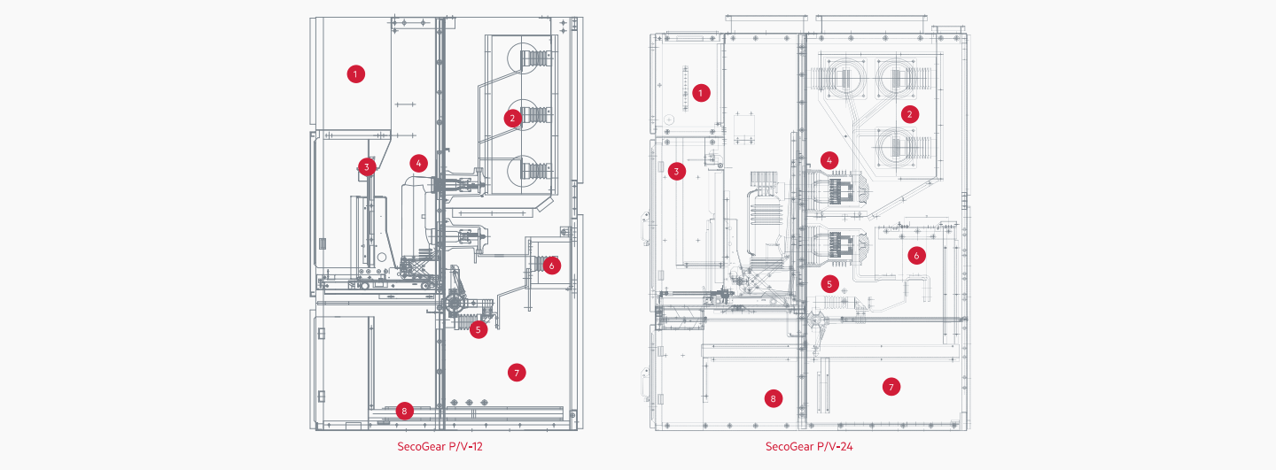
-
low-voltage chamber
The low-voltage chamber is composed of metal partitions with grounding systems, leaving sufficient space for placing control and protection equipment. Each switch is equipped with a completely isolated secondary control line path; Form a continuous low-voltage line channel along the entire switchgear.
-
Busbar room
The busbar room is composed of metal partitions with grounding system. The entire section of the busbar can be insulated, and SecoGearP/V-12 has passed type tests with a rating of up to 5000A and 50kA/4s. SecoGearP/V-24 has passed type tests of 3150A and 31.5kA/s.
-
Vacuum circuit breaker chamber
The circuit breaker room is composed of grounded metal partitions with separate pressure release channels inside. The room provides a safety interlock mechanism to ensure the safety and reliability of vacuum circuit breaker operation. When the circuit breaker room door is closed, the buttons on the panel can be used for operation. The circuit breaker is mechanically interlocked with the cable compartment door, so the cable compartment door can only be opened when the circuit breaker is opened and moved to the test position (while the grounding switch is closed).
-
Institutional valve
When the circuit breaker is in the test position, the valve will automatically close to avoid contact with the static contact. When the circuit breaker is in the working position, the valve automatically opens
-
grounding switch
The grounding switch can be operated from the front of the switchgear. The grounding switch and the circuit breaker handcart are mechanically interlocked, and the grounding switch can only be operated when the circuit breaker is in the test position. At the same time, the grounding switch and cable room are mechanically interlocked to ensure safety.
-
Current transformer
The primary component of the current transformer is completely enclosed in epoxy resin to prevent the entry of pollutants and water vapor, providing excellent protection performance. This transformer can be configured with one or more independent windings to meet the different needs of measurement, metering, and protection.
-
Cable room
The lower part of the cable room is equipped with a bracket to support the cables. Cable clamps are also provided for securing cables. In addition, the metal base plate is separable.
-
Grounding copper busbar
Located at the bottom of the cable room. Passed the corresponding grounding circuit dynamic and thermal stability test.
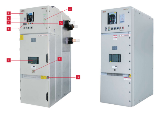
-
01 Low‑voltage Control and Protection Compartment
The panel is equipped with all control switches and indicator lamps for clear visualization and easy operation.
-
02 Relay Protection
Relay protection devices of various brands can be installed according to user requirements.
-
03 Mimic Diagram
Circuit mimic diagram for clear display of operating status.
-
04 Circuit‑breaker Position Indicator Lamps
Circuit‑breaker position indicator lamps show the service/test position of the circuit‑breaker.
-
05 Electrical Operation with Circuit‑breaker Status Indicator Lamps
Indicator lamps for circuit‑breaker open/closed status.
-
06 Voltage Detection System
In compliance with IEC 61243‑5 standard, the switchgear can be optionally equipped with a standard three‑phase voltage detection system for voltage measurement.
-
07 Viewing Window
Viewing window on the door of circuit‑breaker compartment, enabling visual inspection of circuit‑breaker position: (1) Circuit‑breaker status (2) Status of spring‑charged mechanism.
-
08 Circuit‑breaker Trolley Operating Hole
Operating hole for circuit‑breaker rack‑in / rack‑out operations.
-
09 Earthing‑switch Operating Hole
Earthing‑switch open/close, circuit‑breaker open/close command switches; optional LED lamp to indicate the “charged” status of the spring‑charged mechanism.
Product Parameters
| Rated voltage | kv | 3.6 | 12 | 24 |
| Rated power‑frequency withstand voltage (1 min) | kv | 25 | 42 | 65 |
| Rated lightning impulse withstand voltage (1.2/50 μs) | kv | 40 | 75 | 65 |
| Rated frequency | HZ | 50 | 65 | |
| Rated current (main busbar) | A | 630/125011600/2000/2500/3150/4000*5000* | 6301250/1600/2000/2500/3150* | |
| Rated short‑time withstand current (r.m.s., 4 s) | kA | 25/315/40/5025/315 | 25/315 | |
| Rated peak withstand current | kA | 63/80/100(125*N125(135*)IPGX | IPGX | |
| IP protection degree |
enclosure |
IPGX | IPGX | |
| Internal arc classification | G0kAs(50kA/05) | 315kA/1s | ||

- Address: Room 6G, Liangfeng Building, No. 8 Dongfang Road, Pudong New Area, Shanghai
- Phone · +021-58765400
- Fax · +021-58765400-816
- Mail · shdonghu@shdonghu.com